00132214_0
Flow adjustment damper, variant VFR, with actuator (mechanical stops)


00132715_0
Tested to VDI 6022


00131711_0
Actuator with potentiometers


00135027_0
Actuator with mechanical stops


00136817_0
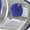
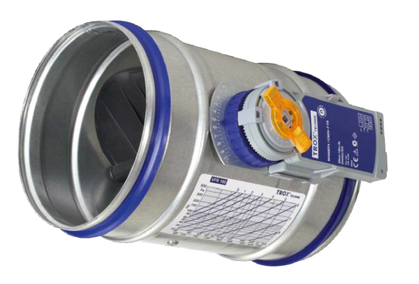
Variant with rotary knob


00132214_0
00132715_0
00131711_0
00135027_0
00136817_0

VFR 

FOR THE RELIABLE BALANCING OF VOLUME FLOW RATES

Circular flow adjustment dampers for the adjustment of volume flow rates and pressures in supply air and extract air systems

  • Each flow adjustment damper carries a diagram with setting values that ensure rapid commissioning on site
  • Suitable for duct pressures up to 1000 Pa.
  • Volume flow rate can be set using a rotary knob and a scale on the outside of the casing
  • Simple retrofit of an actuator
  • Casing air leakage to EN 1751, class C


Optional equipment and accessories

  • Actuator with potentiometer
  • Actuator with mechanical stops

Application

Application

  • Circular flow adjustment dampers Type VFR for the simple balancing of volume flow rates and pressures in air conditioning systems
  • Stepless adjustment of the volume flow rate using a rotary knob with position indicator
  • Simple retrofit of an actuator
  • At the minimum setting (closed position 0) a system pressure dependent leakage flow rate occurs

Special features

  • Diagram with setting values on each flow adjustment damper
  • Simple retrofit of an actuator is possible

Nominal sizes

  • 80, 100, 125, 140, 150, 160, 180 , 200, 224, 250

Description

Construction

  • Galvanised sheet steel
  • A2: Stainless steel

Parts and characteristics

  • Ready-to-install flow adjustment damper
  • Rotary knob with position indicator
  • Stepless adjustment from 0 to 10
  • Diagram with setting values
  • Lip seal

Attachments

  • Min/Max actuators: Actuators for switching between minimum and maximum volume flow rate setpoint values
  • Modulating actuators: Actuators for the stepless adjustment of volume flow rates

Construction features

  • Spigot with lip seal, for circular connecting ducts to EN 1506 or EN 13180
  • Very good dimensional stability due to double grooves
  • Damper blade without seal but with perimeter gap of 3 mm

Materials and surfaces

  • Rotary knob, damper blade and bearings made of plastic, flame retardant (V-0) to UL 94


Galvanised sheet steel construction

  • Casing made of galvanised sheet steel


Stainless steel construction (A2)

  • Casing made of stainless steel 1.4301

Standards and guidelines

  • Hygiene conforms to VDI 6022
  • Casing air leakage to EN 1751, class C

Maintenance

  • Maintenance-free as construction and materials are not subject to wear

Technical information

Function, Technical data, QUICK SIZING, Specification text, Order code, Product relations

  • Function
  • Technical data
  • QUICK SIZING
  • Specification text
  • Order code
  • PRODUCT RELATIONS
Schematic illustration of the VFR 00135860_0
① Damper blade
② Scale
③ Rotary knob
④ Rotary knob locking screw
⑤ Lip seal
⑥ Diagram with setting values


Functional description

For balancing the volume flow rates of duct sections and air terminal devices the differential pressure must be set on the flow adjustment dampers. The value to be set for a certain required volume flow rate at a given differential pressure can be taken from the diagram that each flow adjustment damper carries. This value can then be set using the rotary knob with the position indicator (stepless adjustment between 0 and 10).

Nominal sizes

80 – 250 mm

Volume flow rate range

20 – 485 l/s or 72 – 1746 m³/h

Minimum differential pressure

20 Pa

Maximum differential pressure

1000 Pa

Operating temperature

10 – 50 °C


Closed blade air leakage

Nominal size Δpst [Pa]
Nominal size 100 200 500
Nominal size l/s m³/h l/s m³/h l/s m³/h

80

9

32

13

46

20

72

100

13

45

18

64

28

101

125

16

58

23

82

36

130

140

17

61

25

89

39

140

150

18

66

26

93

41

148

160

21

76

30

107

47

169

180

19

69

27

98

43

155

200

21

74

29

105

46

166

224

22

80

32

114

50

180

250

25

89

35

125

55

198


Quick sizing tables provide a good overview of the room sound pressure levels that can be expected. Approximate intermediate values can be interpolated.

Quick sizing: Sound pressure level

Nominal size Volume flow rate Δpst [Pa]
Nominal size Volume flow rate 10 20 30 50 80 100 200
Nominal size Volume flow rate LPA
Nominal size l/s m³/h dB(A)

80

20

72

25

28

30

32

35

36

41

80

30

108

30

33

35

37

40

41

45

80

40

144

33

36

38

41

43

45

49

80

50

180

36

40

42

44

47

48

53

100

30

109

27

29

31

34

36

38

44

100

45

163

32

35

37

39

42

43

48

100

60

217

36

39

41

44

46

48

52

100

75

272

40

43

45

48

50

52

56

125

50

180

28

31

33

36

39

41

47

125

70

252

33

36

38

41

44

46

51

125

95

342

37

41

43

46

49

50

55

125

120

432

41

45

47

50

53

54

59

140

60

215

25

29

31

34

38

40

47

140

90

323

31

34

37

40

44

45

51

140

120

431

35

39

42

45

48

50

56

140

150

538

39

43

45

49

52

54

59

150

70

252

26

30

32

36

39

41

48

150

105

378

31

35

37

41

44

46

52

150

140

504

35

39

42

45

48

50

56

150

170

612

37

42

44

48

51

53

58

160

80

288

27

30

33

36

39

41

48

160

120

432

33

37

39

42

45

47

53

160

155

558

38

41

44

47

50

51

57

160

195

702

41

45

47

50

53

54

59

180

100

358

25

29

32

35

39

41

48

180

150

540

31

35

38

41

45

47

53

180

200

720

35

39

42

45

48

50

56

180

250

900

38

42

45

48

51

53

59

200

125

450

26

30

33

37

41

43

51

200

185

665

32

36

39

42

46

48

55

200

245

882

36

40

43

47

50

52

59

200

310

1116

39

44

46

50

54

56

62

224

155

557

24

28

31

35

39

41

47

224

230

828

28

32

35

39

42

44

50

224

310

1115

32

36

38

42

45

47

53

224

385

1386

34

38

41

44

48

49

55

250

195

702

24

28

32

36

41

43

52

250

290

1043

28

33

36

40

45

47

56

250

385

1386

31

36

40

44

49

51

59

250

485

1746

34

39

43

47

52

54

62


Circular flow adjustment dampers for the simple balancing of volume flow rates in air conditioning systems, for supply air and extract air, available in 10 nominal sizes.

Suitable for duct pressures up to 1000 Pa.

Ready-to-install unit consists of the casing with damper blade and rotary knob for the stepless adjustment of volume flow rates.

Spigot with lip seal, for circular connecting ducts to EN 1506 or EN 13180.

Casing air leakage to EN 1751, class C.

Special features

  • Diagram with setting values on each flow adjustment damper
  • Simple retrofit of an actuator is possible

Materials and surfaces

  • Rotary knob, damper blade and bearings made of plastic, flame retardant (V-0) to UL 94


Galvanised sheet steel construction

  • Casing made of galvanised sheet steel


Stainless steel construction (A2)

  • Casing made of stainless steel 1.4301

Construction

  • Galvanised sheet steel
  • A2: Stainless steel

Technical data

  • Nominal sizes: 80 to 250 mm
  • Volume flow rate range: 9 to 615 l/s or 32 to 2215 m³/h
  • Minimum differential pressure: 20 Pa
  • Maximum differential pressure: 1000 Pa

Sizing data

  • V _______________________ [m³/h]
  • Δpst _______________________ [Pa]

Air-regenerated noise

  • LPA _______________________ [dB(A)]

This specification text describes the general properties of the product. Texts for variants can be generated with our Easy Product Finder design programme.

00131367_0

 Type
VFR       Flow adjustment damper

 Material
       No entry: galvanised sheet steel
A2       Stainless steel


 Nominal size [mm]
80
100
125
140
150
160
180
200
224
250

 Actuator
       No entry: manual operation
       For example
E01       24 V AC/DC, 3-point, potentiometer
E03       24 V AC/DC, modulating, 0 – 10 V DC, potentiometer
M01       24 V AC/DC, 3-point, mechanical stops

Order example: VFR/160/M01

Nominal size

160 mm

Actuator

24 V AC/DC, mechanical stops


Variants, Attachments, Dimensions and weight, Product details

  • Variants
  • Attachments
  • Dimensions and weight
  • Product details

Attachments

Order code detail Actuator Supply voltage Auxiliary switch

Min/Max actuators


E01

Actuator with potentiometers TROX/Gruner

24 V AC/DC

E02

Actuator with potentiometers TROX/Gruner

230 V AC

M01

Actuator with mechanical stops TROX/Belimo

24 V AC/DC

M02

Actuator with mechanical stops TROX/Belimo

230 V AC

Modulating actuators


E03

Actuator with potentiometers TROX/Gruner

24 V AC/DC


VFR

Nominal size
VFR
m
kg
VFR/.../E0*
m
kg
VFR/.../M0*
m
kg
ØD
mm
80 0.5 0.8 0.7 79
100 0.6 0.9 0.8 99
125 0.7 1.0 0.9 124
140 0.8 1.1 1.0 139
150 0.8 1.1 1.0 149
160 0.8 1.1 1.0 159
180 0.9 1.2 1.1 179
200 1.0 1.3 1.2 199
224 1.2 1.4 1.4 223
250 1.3 1.6 1.5 249


Type VFR – The System 00137021_0
① Flow adjustment damper VFR with rotary knob
② Actuator E0* with potentiometers
③ Actuator M0* with mechanical stops


Installation details, Commissioning, Basic information and nomenclature

  • Installation details
  • Commissioning
  • Basic information and nomenclature
Access to attachments, attached on one side 00149821_0


Installation and commissioning

  • Any installation orientation
  • Volume flow rate setpoint can be set on external scale

Space required

Attachments
Attachments mm

Without actuator

200

200

200

With actuator E0*

200

200

300

With actuator M0*

200

200

230


Diagram with setting values 00134305_0

Diagram to determine the setting values on site (example for nominal size 125)


Principal dimensions

ØD [mm]

Shut-off and flow adjustment dampers made of stainless steel: Outer diameter of the connecting spigot

Shut-off dampers made of plastic: Inside diameter of the connecting spigot

ØD₁ [mm]

Pitch circle diameter of flanges

ØD₂ [mm]

Outer diameter of flanges

ØD₄ [mm]

Inside diameter of the screw holes of flanges

L [mm]

Length of unit including connecting spigot

L₁ [mm]

Length of casing or acoustic cladding

n [ ]

Number of flange screw holes

T [mm]

Flange thickness

m [kg]

Unit weight including the minimum required attachments

Acoustic data

LPA [dB(A)]

A-weighted sound pressure level of air-regenerated noise of the shut-off or flow adjustment damper, system attenuation taken into account


All sound pressure levels are based on 20 μPa.

Volume flow rates

V [m³/h] and [l/s]

Volume flow rate

Differential pressure

Δpst [Pa]

Static differential pressure

Downloads

product information

certificates

References

production {"X-Frame-Options"=>"SAMEORIGIN", "X-XSS-Protection"=>"1; mode=block", "X-Content-Type-Options"=>"nosniff", "X-Download-Options"=>"noopen", "X-Permitted-Cross-Domain-Policies"=>"none", "Referrer-Policy"=>"strict-origin-when-cross-origin", "Content-Security-Policy"=>"frame-ancestors 'self' https://api.scrivito.com https://punchoutcommerce.com https://www.trox.de https://trox-extern.com https://psp40.onventis.com https://psp22.onventis.com https://trox4u.troxgroup.com", "Strict-Transport-Security"=>"max-age=31536000; includeSubDomains", "Content-Type"=>"text/html; charset=utf-8"}

Share page

Recommend this page

Recommend this page by sending a link by mail.

Fields marked with an (*) are required fields.

Share page

Thank you for your recommendation!

Your recommendation has been sent and should arrive shortly.

Contact

We are here for you

Please specify your message and type of request.
Tel.: +61 (02) 8923 2551

Fields marked with an (*) are required fields.

Contact

Thank you for your message!

Your message is send and will be processed shortly.
Our department for Service-Requests will contact you asap.
For general question regarding products or services you can also call:
Tel.: +61 (02) 8923 2551

Contact

We are here for you

Please specify your message and type of request.
Tel.: +61 (02) 8923 2551

Attachment (max. 10MB)

Fields marked with an (*) are required fields.

Contact

Thank you for your message!

Your message is send and will be processed shortly.
Our department for Service-Requests will contact you asap.
For general question regarding products or services you can also call:
Tel.: +61 (02) 8923 2551