VAV terminal unit type TVR with an Easy controller
Application
Special features
Nominal sizes
Variants
Construction
Parts and characteristics
Attachments
Accessories
Useful additions
Construction features
Materials and surfaces
Galvanised sheet steel construction
Powder-coated construction (P1)
Stainless steel construction (A2)
Variant with acoustic cladding (-D)
Mineral wool
Standards and guidelines
Fulfils the hygiene requirements of
Casing leakage
Closed blade air leakage:
NS 100
NS 125 – 160
NS > 160
Maintenance
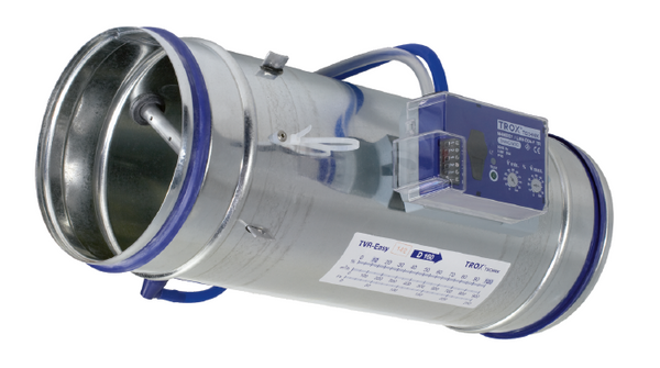
① Effective pressure sensor
② Damper blade
③ Double lip seal
④ Control components, e.g. an Easy controller
The VAV terminal unit is fitted with an effective pressure sensor for measuring the volume flow rate. The control components (attachments) include an effective pressure transducer that transforms the effective pressure into an electric signal, a controller, and an actuator; the control functions can be achieved with an Easy controller or with a Compact controller or with individual components (Universal or LABCONTROL). For most applications, the setpoint value comes from a room temperature controller. The controller compares the actual value with the setpoint value and alters the control signal of the actuator if there is a difference between the two values.
Nominal sizes | 100 – 400 mm |
Volume flow rate range | 34 – 7591 m³/h or 10 – 2108 l/s |
Volume flow rate control range (unit for dynamic effective pressure measurements) | Approx. 10 – 100 % of the nominal volume flow rate |
Volume flow rate control range (unit for static effective pressure measurements) | approx. 15 to 100 % of the nominal volume flow rate |
Minimum differential pressure | Up to 117 Pa (without circular silencer) |
Maximum differential pressure | 1000 Pa |
Operating temperature | 10 to 50 °C |
Quick sizing tables provide a good overview of the minimum differential pressures, the volume flow rate accuracy and the room sound pressure levels that can be expected. Intermediate values may be achieved by interpolation.
The sound power levels for calculating the sound pressure levels were measured in the TROX laboratory according to DIN EN ISO 5135 - see "Basic information and nomenclature".
Precise results and spectral data for all control components can be calculated with our Easy Product Finder design program. The first selection criteria for the nominal size are the actual volume flow rates qvmin and qvmax.
Volume flow rate ranges and minimum differential pressure values
The minimum differential pressure of VAV terminal units is an important factor in designing the ductwork and in rating the fan including speed control. It must be ensured that for all operating conditions and for all terminal units a sufficient pressure differential is applied to each controller (Δpstat,min). The measurement points for fan speed control must be selected accordingly. The volume flow rates given for VAV terminal units depend on the nominal size and on the control component (attachment) that is installed.
Volume flow rate ranges and minimum differential pressure values
Control component for dynamic pressure measurements – Easy (potentiometers)
Attachment: Easy
NS | qv [l/s] | qv [m³/h] | Δpstmin [Pa] | Δqv [±%] | |||
---|---|---|---|---|---|---|---|
① | ② | ③ | ④ | ||||
100 | 10 | 34 | 1 | 1 | 1 | 2 | 16 |
100 | 38 | 136 | 12 | 14 | 16 | 19 | 9 |
100 | 66 | 239 | 35 | 42 | 50 | 57 | 7 |
100 | 94 | 341 | 71 | 86 | 101 | 116 | 6 |
125 | 16 | 55 | 1 | 1 | 1 | 2 | 16 |
125 | 62 | 223 | 12 | 14 | 16 | 18 | 8 |
125 | 108 | 390 | 37 | 43 | 49 | 55 | 7 |
125 | 155 | 558 | 75 | 87 | 100 | 112 | 6 |
160 | 25 | 88 | 1 | 1 | 1 | 1 | 16 |
160 | 99 | 357 | 11 | 13 | 14 | 15 | 9 |
160 | 174 | 627 | 34 | 38 | 42 | 46 | 7 |
160 | 248 | 896 | 69 | 77 | 86 | 94 | 6 |
200 | 40 | 143 | 1 | 1 | 1 | 1 | 16 |
200 | 162 | 582 | 11 | 12 | 13 | 14 | 8 |
200 | 283 | 1020 | 33 | 36 | 40 | 43 | 7 |
200 | 405 | 1459 | 67 | 74 | 81 | 87 | 6 |
250 | 60 | 216 | 1 | 1 | 1 | 1 | 16 |
250 | 245 | 881 | 8 | 9 | 9 | 10 | 9 |
250 | 430 | 1547 | 23 | 25 | 28 | 30 | 7 |
250 | 614 | 2212 | 46 | 51 | 56 | 61 | 6 |
315 | 100 | 359 | 1 | 1 | 1 | 1 | 16 |
315 | 407 | 1464 | 5 | 6 | 7 | 7 | 8 |
315 | 713 | 2568 | 15 | 17 | 19 | 21 | 7 |
315 | 1020 | 3673 | 31 | 35 | 39 | 42 | 6 |
400 | 165 | 591 | 1 | 1 | 1 | 1 | 16 |
400 | 670 | 2413 | 4 | 5 | 5 | 6 | 8 |
400 | 1177 | 4236 | 12 | 14 | 15 | 16 | 7 |
400 | 1682 | 6058 | 25 | 27 | 30 | 33 | 6 |
① Basic unit
② Basic unit with circular silencer CS/CF, insulation thickness 50 mm, length 500 mm
③ Basic unit with circular silencer CS/CF, insulation thickness 50 mm, length 1000 mm
④ Basic unit with circular silencer CS/CF, insulation thickness 50 mm, length 1500 mm
Volume flow rate ranges and minimum differential pressure values
Control component dynamic measurement principle – qv Extended
Attachments: BC0, BL0 **, BM0, BM0-J6
NS | qv [l/s] | qv [m³/h] | Δpstmin [Pa] | Δqv [±%] | |||
---|---|---|---|---|---|---|---|
① | ② | ③ | ④ | ||||
100 | 10 | 34 | 1 | 1 | 1 | 2 | 16 |
100 | 46 | 165 | 17 | 20 | 24 | 28 | 8 |
100 | 83 | 297 | 54 | 65 | 77 | 88 | 6 |
100 | 118 | 428 | 111 | 135 | 158 | 182 | 5 |
125 | 16 | 55 | 1 | 1 | 1 | 2 | 16 |
125 | 75 | 270 | 18 | 21 | 24 | 27 | 8 |
125 | 134 | 484 | 57 | 66 | 75 | 84 | 6 |
125 | 194 | 699 | 117 | 137 | 156 | 175 | 5 |
160 | 25 | 88 | 1 | 1 | 1 | 1 | 16 |
160 | 120 | 433 | 17 | 18 | 20 | 22 | 8 |
160 | 216 | 777 | 52 | 58 | 64 | 71 | 6 |
160 | 311 | 1122 | 108 | 121 | 134 | 147 | 5 |
200 | 40 | 143 | 1 | 1 | 1 | 1 | 16 |
200 | 196 | 705 | 16 | 18 | 19 | 21 | 8 |
200 | 352 | 1266 | 51 | 56 | 61 | 66 | 6 |
200 | 507 | 1828 | 105 | 116 | 126 | 137 | 5 |
250 | 60 | 216 | 1 | 1 | 1 | 1 | 16 |
250 | 297 | 1068 | 11 | 12 | 13 | 15 | 8 |
250 | 533 | 1919 | 35 | 38 | 42 | 46 | 6 |
250 | 769 | 2771 | 72 | 80 | 87 | 95 | 5 |
315 | 100 | 359 | 1 | 1 | 1 | 1 | 16 |
315 | 493 | 1774 | 8 | 9 | 9 | 10 | 8 |
315 | 886 | 3188 | 24 | 26 | 29 | 32 | 6 |
315 | 1278 | 4603 | 49 | 55 | 60 | 66 | 5 |
400 | 165 | 591 | 1 | 1 | 1 | 1 | 16 |
400 | 812 | 2924 | 6 | 7 | 7 | 8 | 8 |
400 | 1461 | 5258 | 19 | 21 | 23 | 25 | 6 |
400 | 2108 | 7591 | 38 | 43 | 47 | 51 | 5 |
① Basic unit
② Basic unit with circular silencer CS/CF, insulation thickness 50 mm, length 500 mm
③ Basic unit with circular silencer CS/CF, insulation thickness 50 mm, length 1000 mm
④ Basic unit with circular silencer CS/CF, insulation thickness 50 mm, length 1500 mm
** Control component to be discontinued - do not include in new projects
Volume flow rate ranges and minimum differential pressure values
Control component for dynamic pressure measurements – qv standard
Attachments: BUDN, BUDNF, LN0, LK0, LB0, XB0, XB4, (B13 *, B1B *)
NS | qv [l/s] | qv [m³/h] | Δpstmin [Pa] | Δqv [±%] | |||
---|---|---|---|---|---|---|---|
① | ② | ③ | ④ | ||||
100 | 10 | 34 | 1 | 1 | 1 | 2 | 16 |
100 | 39 | 141 | 12 | 15 | 18 | 20 | 9 |
100 | 69 | 247 | 37 | 45 | 53 | 61 | 7 |
100 | 98 | 354 | 76 | 92 | 109 | 125 | 6 |
125 | 16 | 55 | 1 | 1 | 1 | 2 | 16 |
125 | 64 | 229 | 13 | 15 | 17 | 19 | 8 |
125 | 112 | 404 | 40 | 46 | 52 | 59 | 7 |
125 | 160 | 578 | 80 | 94 | 107 | 120 | 6 |
160 | 25 | 88 | 1 | 1 | 1 | 1 | 16 |
160 | 102 | 368 | 12 | 13 | 15 | 16 | 8 |
160 | 180 | 648 | 36 | 41 | 45 | 49 | 7 |
160 | 257 | 928 | 74 | 83 | 92 | 101 | 6 |
200 | 40 | 143 | 1 | 1 | 1 | 1 | 16 |
200 | 166 | 599 | 12 | 13 | 14 | 15 | 8 |
200 | 293 | 1056 | 35 | 39 | 42 | 46 | 6 |
200 | 420 | 1512 | 72 | 79 | 86 | 94 | 6 |
250 | 60 | 216 | 1 | 1 | 1 | 1 | 16 |
250 | 252 | 908 | 8 | 9 | 10 | 11 | 8 |
250 | 444 | 1600 | 24 | 27 | 29 | 32 | 7 |
250 | 636 | 2292 | 49 | 55 | 60 | 65 | 6 |
315 | 100 | 359 | 1 | 1 | 1 | 1 | 16 |
315 | 419 | 1508 | 6 | 6 | 7 | 8 | 8 |
315 | 738 | 2658 | 17 | 19 | 20 | 22 | 6 |
315 | 1057 | 3807 | 33 | 37 | 42 | 46 | 6 |
400 | 165 | 591 | 1 | 1 | 1 | 1 | 16 |
400 | 691 | 2487 | 5 | 5 | 5 | 6 | 8 |
400 | 1218 | 4383 | 13 | 15 | 16 | 17 | 6 |
400 | 1744 | 6279 | 26 | 29 | 32 | 35 | 5 |
① Basic unit
② Basic unit with circular silencer CS/CF, insulation thickness 50 mm, length 500 mm
③ Basic unit with circular silencer CS/CF, insulation thickness 50 mm, length 1000 mm
④ Basic unit with circular silencer CS/CF, insulation thickness 50 mm, length 1500 mm
* Control component has been discontinued
Volume flow rate ranges and minimum differential pressure values
Control component of static measurement principle
Attachments: BUSN, BUSNF, BUSS, XD0, XD4, TUN, TUNF, TUS, TUSD, ELAB (BP3 *, BPG *, BPB *, BB3 *, BBB *)
NS | qv [l/s] | qv [m³/h] | Δpstmin [Pa] | Δqv [±%] | |||
---|---|---|---|---|---|---|---|
① | ② | ③ | ④ | ||||
100 | 14 | 50 | 2 | 2 | 3 | 3 | 14 |
100 | 42 | 151 | 14 | 17 | 20 | 23 | 8 |
100 | 70 | 253 | 39 | 47 | 56 | 64 | 7 |
100 | 98 | 354 | 76 | 92 | 109 | 125 | 6 |
125 | 23 | 81 | 2 | 2 | 3 | 3 | 13 |
125 | 69 | 247 | 15 | 18 | 20 | 22 | 8 |
125 | 114 | 412 | 41 | 48 | 54 | 61 | 6 |
125 | 160 | 578 | 80 | 94 | 107 | 120 | 6 |
160 | 36 | 129 | 2 | 2 | 2 | 2 | 14 |
160 | 110 | 395 | 14 | 15 | 17 | 19 | 8 |
160 | 184 | 662 | 38 | 42 | 47 | 51 | 7 |
160 | 257 | 928 | 74 | 83 | 92 | 101 | 6 |
200 | 59 | 210 | 2 | 2 | 2 | 2 | 13 |
200 | 179 | 644 | 13 | 15 | 16 | 17 | 8 |
200 | 299 | 1078 | 37 | 41 | 44 | 48 | 6 |
200 | 420 | 1512 | 72 | 79 | 86 | 94 | 6 |
250 | 89 | 318 | 1 | 2 | 2 | 2 | 14 |
250 | 271 | 976 | 9 | 10 | 11 | 12 | 8 |
250 | 454 | 1634 | 25 | 28 | 31 | 33 | 7 |
250 | 636 | 2292 | 49 | 55 | 60 | 65 | 6 |
315 | 147 | 529 | 1 | 1 | 1 | 1 | 13 |
315 | 451 | 1622 | 6 | 7 | 8 | 9 | 8 |
315 | 754 | 2714 | 17 | 19 | 21 | 23 | 6 |
315 | 1057 | 3807 | 33 | 37 | 42 | 46 | 6 |
400 | 242 | 871 | 1 | 1 | 1 | 1 | 13 |
400 | 743 | 2674 | 5 | 6 | 6 | 7 | 8 |
400 | 1243 | 4476 | 14 | 15 | 17 | 18 | 6 |
400 | 1744 | 6279 | 26 | 29 | 32 | 35 | 5 |
① Basic unit
② Basic unit with circular silencer CS/CF, insulation thickness 50 mm, length 500 mm
③ Basic unit with circular silencer CS/CF, insulation thickness 50 mm, length 1000 mm
④ Basic unit with circular silencer CS/CF, insulation thickness 50 mm, length 1500 mm
* Control component has been discontinued
Quick sizing table for sound pressure level
The quick sizing tables are based on generally accepted attenuation and insulation levels. If the sound pressure level exceeds the required level, a larger air terminal unit and/or a silencer or acoustic cladding is required. For more information on the acoustic data, see basic information and nomenclature.
Quick sizing table for air-regenerated noise LPA
Controller including silencer
(total flow rate range of type)
NS | qv [l/s] | qv [m³/h] | 150 Pa | 500 Pa | ||||||
---|---|---|---|---|---|---|---|---|---|---|
① | ② | ③ | ④ | ① | ② | ③ | ④ | |||
100 | 10 | 34 | 32 | 18 | < 15 | < 15 | 43 | 27 | 20 | 15 |
100 | 46 | 165 | 48 | 36 | 31 | 27 | 58 | 45 | 38 | 34 |
100 | 83 | 297 | 53 | 42 | 37 | 33 | 64 | 51 | 45 | 41 |
100 | 118 | 428 | 57 | 45 | n.V. | n.V. | 67 | 55 | 49 | 45 |
125 | 16 | 55 | 34 | 19 | < 15 | < 15 | 46 | 30 | 23 | 18 |
125 | 75 | 270 | 47 | 36 | 31 | 28 | 59 | 46 | 41 | 37 |
125 | 134 | 484 | 52 | 42 | 37 | 34 | 63 | 52 | 47 | 43 |
125 | 194 | 699 | 53 | 44 | n.V. | n.V. | 65 | 54 | 49 | 46 |
160 | 25 | 88 | 39 | 25 | 19 | 15 | 51 | 36 | 30 | 25 |
160 | 120 | 433 | 50 | 39 | 35 | 32 | 62 | 50 | 45 | 42 |
160 | 216 | 777 | 52 | 42 | 38 | 35 | 64 | 53 | 49 | 46 |
160 | 311 | 1122 | 53 | 44 | 40 | 37 | 65 | 55 | 51 | 47 |
200 | 40 | 143 | 41 | 30 | 24 | 20 | 51 | 41 | 36 | 31 |
200 | 196 | 705 | 50 | 42 | 38 | 36 | 61 | 52 | 48 | 44 |
200 | 352 | 1266 | 52 | 44 | 41 | 39 | 62 | 54 | 51 | 48 |
200 | 507 | 1828 | 52 | 46 | 43 | 41 | 63 | 56 | 52 | 50 |
250 | 60 | 216 | 41 | 32 | 26 | 23 | 51 | 41 | 37 | 33 |
250 | 297 | 1068 | 48 | 41 | 37 | 35 | 57 | 51 | 47 | 45 |
250 | 533 | 1919 | 49 | 43 | 40 | 38 | 58 | 53 | 50 | 47 |
250 | 769 | 2771 | 49 | 44 | 42 | 40 | 59 | 54 | 51 | 48 |
315 | 100 | 359 | 44 | 36 | 31 | 27 | 54 | 47 | 42 | 37 |
315 | 493 | 1774 | 49 | 42 | 39 | 36 | 60 | 53 | 49 | 46 |
315 | 886 | 3188 | 50 | 44 | 41 | 39 | 61 | 55 | 51 | 49 |
315 | 1278 | 4603 | 51 | 46 | 43 | 41 | 62 | 56 | 53 | 50 |
400 | 165 | 591 | 45 | 38 | 33 | 29 | 58 | 53 | 48 | 43 |
400 | 812 | 2924 | 46 | 40 | 36 | 34 | 59 | 54 | 50 | 47 |
400 | 1461 | 5258 | 46 | 41 | 38 | 36 | 60 | 55 | 51 | 48 |
400 | 2108 | 7591 | 47 | 42 | 40 | 39 | 60 | 55 | 52 | 49 |
Air-regenerated noise LPA [dB] at static differential pressure Δpst of 150 or 500 Pa
① Basic unit
② Basic unit with circular silencer CS/CF, insulation thickness 50 mm, length 500 mm
③ Basic unit with circular silencer CS/CF, insulation thickness 50 mm, length 1000 mm
④ Basic unit with circular silencer CS/CF, insulation thickness 50 mm, length 1500 mm
n.a.: The specified static differential pressure Δpst is lower than the minimum differential pressure Δpst min.
Quick sizing table for case-radiated noise LPA
Controller including acoustic cladding
(total flow rate range of type)
NS | qv [l/s] | qv [m³/h] | 150 Pa | 500 Pa | ||
---|---|---|---|---|---|---|
① | ② | ① | ② | |||
100 | 10 | 34 | 15 | < 15 | 26 | 15 |
100 | 46 | 165 | 31 | 20 | 41 | 30 |
100 | 83 | 297 | 36 | 25 | 47 | 36 |
100 | 118 | 428 | 40 | 29 | 50 | 39 |
125 | 16 | 55 | 17 | < 15 | 28 | 17 |
125 | 75 | 270 | 30 | 19 | 41 | 30 |
125 | 134 | 484 | 35 | 24 | 46 | 35 |
125 | 194 | 699 | 38 | 27 | 49 | 38 |
160 | 25 | 88 | 19 | < 15 | 30 | 23 |
160 | 120 | 433 | 30 | 23 | 42 | 35 |
160 | 216 | 777 | 34 | 27 | 46 | 39 |
160 | 311 | 1122 | 37 | 30 | 48 | 41 |
200 | 40 | 143 | 21 | < 15 | 31 | 16 |
200 | 196 | 705 | 32 | 17 | 42 | 27 |
200 | 352 | 1266 | 36 | 21 | 46 | 31 |
200 | 507 | 1828 | 39 | 24 | 49 | 34 |
250 | 60 | 216 | 25 | < 15 | 34 | 19 |
250 | 297 | 1068 | 35 | 20 | 45 | 30 |
250 | 533 | 1919 | 39 | 24 | 48 | 33 |
250 | 769 | 2771 | 41 | 26 | 51 | 36 |
315 | 100 | 359 | 29 | < 15 | 39 | 21 |
315 | 493 | 1774 | 40 | 22 | 50 | 32 |
315 | 886 | 3188 | 44 | 26 | 54 | 36 |
315 | 1278 | 4603 | 46 | 29 | 57 | 39 |
400 | 165 | 591 | 30 | < 15 | 43 | 27 |
400 | 812 | 2924 | 39 | 23 | 52 | 36 |
400 | 1461 | 5258 | 42 | 26 | 55 | 39 |
400 | 2108 | 7591 | 44 | 28 | 57 | 41 |
Case-radiated noise LPA [dB] at static differential pressure Δpst of 150 or 500 Pa
① Basic unit
② Basic unit with acoustic cladding
n.a.: The specified static differential pressure Δpst is lower than the minimum differential pressure Δpst min.
Note:
Information on case-radiated noise for combinations of basic unit and optional acoustic cladding and secondary silencer can be found in the Easy Product Finder design program.
Circular VAV terminal units for variable and constant air volume systems, suitable for supply or extract air, available in 7 nominal sizes.
High control accuracy (even with upstream bend R = 1D).
Ready-to-commission unit which consists of the mechanical parts and the electronic control components Each unit contains an averaging effective pressure sensor for volume flow rate measurement, and a control damper blade. Factory mounted control components complete with wiring and tubing.
Effective pressure sensor with 3 mm measuring holes, hence resistant to contamination.
Position of the damper blade indicated externally at shaft extension. The damper blade is factory set to open position, which allows a ventilation airflow even without control; this does not apply to variants with defined safe position NC (normally closed).
Meets the hygiene requirements of EN 16798, Part 3, of VDI 6022, Sheet 1, and of DIN 1946, Part 4.
Special features
Materials and surfaces
Connection
Equivalence criteria
Technical data
Closed blade air leakage, class 2, 3 or 4 depending on nominal size.
Specification text for attachment
Variable volume flow control with electronic Easy controller to connect an external control signal; actual value signal can be integrated into the central BMS.
Sizing data
Air-regenerated noise
Case-radiated noise
TVR | – | D | / | 200 | / | D2 | / | Easy |
| | | | | | | | | | ||||
1 | 2 | 5 | 6 | 7 | ||||
Acoustic cladding | Without |
Material | Galvanised sheet steel |
Nominal size | 125 mm |
Duct connection | Push-fit |
Accessories | Double lip seal both sides |
Attachments (control components) | Easy controller; volume flow controller, dynamic, analogue interface, setting of qvmin and qvmax with potentiometers |
TVR | – | D | – | … | – | FL | / | 160 | / | G2 | / | XD4 | / | V | 0 | / | 200 – 900 [m³/h] | / | NO |
| | | | | | | | | | | | | | | | | | | | | | |||||||||
1 | 2 | 3 | 4 | 5 | 6 | 7 | 9 | 10 | 11 | 12 | |||||||||
Acoustic cladding | Without |
Material | Galvanised sheet steel |
Duct connection | Push-fit |
Nominal size | 200 mm |
Accessories | Without |
Attachments (control components) | VARYCONTROL Universal controller; static transducer; analogue control; safe position with spring return |
Operating mode | Variable operation with setpoint value range qvmin – qvmax |
Signal voltage range | 2 – 10 V DC |
Volume flow rate | qvmin = 500 m³/h qvmax = 1200 m³/h |
Damper blade position | NO power off to OPEN |
TVR | – | D | – | … | – | FL | / | 160 | / | G2 | / | TUNF | / | RS | / | M | / | 0 | / | UMZ | / | … | / | NC |
| | | | | | | | | | | | | | | | | | | | | | | | | | ||||||||||||
1 | 2 | 3 | 4 | 5 | 6 | 7 | 8 | 9 | 10 | 11 | 12 | 13 | ||||||||||||
TVR VAV terminal unit
2 Acoustic cladding
No entry required: None
D With acoustic cladding
3 Material
No entry: galvanised sheet steel
P1 Powder-coated RAL 7001, silver grey
A2 Stainless steel construction
4 Duct connection
No entry: push-fit, suitable for ducts according to EN
1506; with groove for optional lip seal
FL Flange both ends (not for TVR-D-P1)
5 Nominal size [mm]
100, 125, 160, 200, 250, 315, 400
6 Accessories
No entry required: None
D2 Double lip seal both sides
G2 Matching flanges both sides
7 Attachments (control components)
TROX UNIVERSAL controller with
TUN Actuator (150 s)
TUNF Spring return actuator (150 s)
TUS Fast-running actuator (3 s)
TUSD Fast-running actuator (3 s), with digital communication interface (TROX HPD)
8 Equipment function
Room control
RS Supply air control (Room Supply)
RE Extract air control (Room Extract)
9 Volume flow rate setting
M Master (RMF function)S Slave
F Constant flow rate controller
10 Signal voltage range
0 0 – 10 V DC
2 2 – 10 V DC
11 Expansion of attachments
Option 1: Power supply
No entry required: 24 V AC/DC
T EM-TRF for 230 V AC
U EM-TRF-USV for 230 V
AC, provides uninterruptible power supply (UPS)
Option 2: Digital communication interface
No entry required: None
B EM-BAC-MOD-01 for BACnet MS/TP
M EM-BAC-MOD-01 for Modbus RTU
I EM-IP: EM-IP for BACnet/IP, Modbus/IP and web server
R EM-IP with real time clock
Option 3: Automatic zero point correction
No entry required: None
Z EM-AUTOZERO with solenoid valve
12 Operating values [m³/h or l/s] Master (RMF function)qᵥmin: minimum volume flow rateqᵥmax: maximum volume flow rateqᵥconst_Supply air: constant supply airqᵥconst_Extract air: constant extract airqᵥDiff: Supply air/extract air difference Constant valueqᵥconst: constant volume flow rate SlaveNo entry required
13 Damper blade position
Only spring return actuators
NO Power off to OPEN
NC Power off to CLOSE
Useful additions
Room control panel
BE-LCD 40-character display
Acoustic cladding | Without |
Material | Galvanised sheet steel |
Duct connection | Flanges on both ends |
Nominal size | 250 mm |
Accessories | Without |
Attachments (control components) | TROX UNIVERSAL controller with spring return actuator; static transducer; analogue interface |
Equipment function | Room control, extract air |
Volume flow rate setting | Master |
Signal voltage range | 0 – 10 V DC |
Operating values | qvmin = 306 m³/h qvmax = 2205 m³/h |
Damper blade position | NC Power off to CLOSE |
TVR | – | D | – | … | – | FL | / | 160 | / | G2 | / | XF4 | / | PDS | / | V | / | 0 | / | 300-500 [Pa] | / | NO |
| | | | | | | | | | | | | | | | | | | | | | | | |||||||||||
1 | 2 | 3 | 4 | 5 | 6 | 7 | 8 | 9 | 10 | 11 | 12 |
Acoustic cladding | Without |
Material | Galvanised sheet steel |
Duct connection | Flanges on both ends |
Nominal size | 250 mm |
Accessories | Matching flanges both sides |
Attachments (control components) | VARYCONTROL Universal controller for duct pressure; analogue interface |
Equipment function | Duct pressure control, supply air |
Operating mode | Constant value mode |
Signal voltage range | 0 – 10 V DC |
Operating value | ∆pconst = 450 Pa |
Damper blade position | NC Power off to CLOSE |
TVR | – | D | – | … | – | FL | / | 160 | / | G2 | / | TUNF | / | PRS | / | MFP | / | 0 | / | UMZ | / | … | / | NC |
| | | | | | | | | | | | | | | | | | | | | | | | | | ||||||||||||
1 | 2 | 3 | 4 | 5 | 6 | 7 | 8 | 9 | 10 | 11 | 12 | 13 | ||||||||||||
2 Acoustic cladding
No entry required: None
D With acoustic cladding
3 Material
No entry: galvanised sheet steel
P1 Powder-coated RAL 7001, silver grey
A2 Stainless steel construction
4 Duct connection
No entry: push-fit, suitable for ducts according to EN 1506; with groove for optional lip seal
FL Flange both ends (not for TVR-D-P1)
5 Nominal size [mm]
100, 125, 160, 200, 250, 315, 400
6 Accessories
No entry required: None
D2 Double lip seal both sides
G2 Matching flanges both sides
7 Attachments (control components)
TROX UNIVERSAL controller with
TUN Actuator (150 s)
TUNF Spring return actuator (150 s)
TUS Fast-running actuator (3 s)
TUSD Fast-running actuator (3 s), with digital communication interface (TROX HPD)
8 Equipment function
Pressure control
PRS Room pressure control, supply air
PRE Room pressure control, extract air
PDS Duct pressure control, supply air
PDE Duct pressure control, extract air
9 Differential pressure setting
MFP Master, constant pressure control
MVP Master, variable differential pressure control
SFP Slave, constant pressure control
SVP Slave, variable differential pressure control
10 Signal voltage range
0 0 – 10 V DC
2 2 – 10 V DC
11 Expansion of attachments
Option 1: Power supply
No entry required: 24 V AC/DC
T EM-TRF for 230 V AC
U EM-TRF-USV for 230 V AC, provides uninterruptible power supply (UPS)
Option 2: Digital communication interface
No entry required: None
B EM-BAC-MOD-01 for BACnet MS/TP
M EM-BAC-MOD-01 for Modbus RTU
I EM-IP: EM-IP for BACnet/IP, Modbus/IP and web server
R EM-IP with real time clock Option 3: Volume flow rate measurement
No entry required: None
V EM-V Volume flow rate measurement for differential pressure control
Option 4: Automatic zero point correction
No entry required: None
Z EM-AUTOZERO with solenoid valve (only with V)
12 Operating values [Pa, m³/h or l/s]
Slave SVP
Δpmin: minimum differential pressure
Δpmax: maximum differential pressure
Slave SFP
Δpconst: Constant differential pressure
Master MVP and MFP – same as slave, but additionally:
qᵥmin: minimum volume flow rate
qᵥmax: maximum volume flow rate
qᵥconst_Supply air: constant supply air
qᵥconst_Extract air: constant extract air
qᵥDiff: Supply air/extract air difference
13 Damper blade position
Only spring return actuators
NO Power off to OPEN
NC Power off to CLOSE
Useful additions
Room control panel
BE-LCD 40-character display
Differential pressure transducers for room pressure control or duct pressure controlto be ordered separately, e.g.PT-699
For room pressure control
PT-699-DUCT For duct pressure control, including tube and pressure tap
Order example: TVR/160/D2/TUS/PDS/MFP/2/TB/250 Pa
Acoustic cladding | Without |
Material | Galvanised sheet steel |
Duct connection | Push-fit |
Nominal size | 160 mm |
Accessories | Double lip seal both sides |
Attachments (control components) | TROX UNIVERSAL controller with fast-running actuator, analogue interface |
Equipment function | Duct pressure control, supply air |
Differential pressure setting | Master, constant value control |
Signal voltage range | 2 – 10 V DC |
Expansion modules | With expansion module EM-TRF, 230 V AC transformerwith expansion module EM-BAC-MOD, Communication interface for BACnet MS/TP |
Operating value | ∆pconst = 250 Pa |
TVR | – | D | – | … | – | FL | / | 160 | / | G2 | / | ELAB | / | S | / | RS | / | UMZ | / | LAB | / | … |
| | | | | | | | | | | | | | | | | | | | | | | | |||||||||||
1 | 2 | 3 | 4 | 5 | 6 | 7 | 8 | 9 | 11 | 12 | 13 |
2 Acoustic cladding
No entry required: None
D With acoustic cladding
3 Material
No entry: galvanised sheet steel
P1 Powder-coated RAL 7001, silver grey
A2 Stainless steel construction
4 Duct connection
No entry: push-fit, suitable for ducts according to EN 1506; with groove for optional lip seal
FL Flange both ends (not for TVR-D-P1)
5 Nominal size [mm]
100, 125, 160, 200, 250, 315, 400
6 Accessories
No entry required: None
D2 Double lip seal both sides
G2 Matching flange on both ends
7 Attachments (control components)
ELAB EASYLAB controller TCU3
8 ActuatorsS Fast-running actuator (3 s)
SD Fast-running actuator (3 s) with digital communication interface (TROX HPD)
9 Equipment function
Room control
RS Supply air control (Room Supply)
RE Extract air control (Room Exhaust)
PC Differential pressure control (Pressure Control)
11 Expansion modules
Option 1: Power supply
No entry required: 24 V AC/DC
T EM-TRF for 230 V AC
U EM-TRF-USV for 230 V AC, provides uninterruptible power supply (UPS)
Option 2: Digital communication interface
No entry required: None
B EM-BAC-MOD-01 for BACnet MS/TP
M EM-BAC-MOD-01 for Modbus RTU
I EM-IP for BACnet/IP, Modbus/IP and web server
R EM-IP with real time clock
Option 3: Automatic zero point correction
No entry required: None
Z EM-AUTOZERO Solenoid valve for automatic zero point correction
12 Additional functions
Without room management function
LAB Extract air led system (laboratories)
CLR Supply air led system (clean rooms)
With room management function
LAB-RMF Extract air led system
CLR-RMF Supply air led system
13 Operating values [m³/h or l/s, Pa]
(only required when room management function is active)
Total extract air/supply air of room:
qv1: Standard mode
qv2: reduced operation
qv3: increased operation
qv4: constant supply air
qv5: constant extract air
qv6: Supply air/extract air difference
ΔpSet: Setpoint pressure (only with differential pressure control)
Useful additions
Room control panel (only for devices with RMF)
BE-LCD 40-character display
Differential pressure transducer for room pressure control equipment function must be ordered separately, e.g.
PT-699 Measuring range ±50 Pa or ±100 Pa
PT-GB604 Measuring range ±100 Pa
Order example: TVR-D-FL/200/D2/ELAB/SD/RS/MZ/LAB-RMF/2000/1500/2500/100/100/200
Acoustic cladding | With |
Duct connection | Flanges on both ends |
Material | galvanised sheet steel |
Nominal size | 200 mm |
Accessories | Double lip seal both sides |
Attachments (control components) | EASYLAB controller TCU3 |
Actuator | Fast-running actuator (3 s) with digital communication interface (TROX HPD) |
Equipment function | Supply air control |
Expansion modules | Expansion modules EM-BAC-MOD for Modbus RTU and EM-AUTOZERO for automatic zero point correction |
Additional function | Room management function for extract air led system, e.g. laboratory |
Operating values | Standard mode = 2000 m³/h Reduced operation = 1500 m³/h Increased operation = 2500 m³/h Constant supply air =100 m³/h Constant extract air = 100 m³/h supply air/extract air difference = 200 m³/h |
TVR | – | D | – | … | – | FL | / | 160 | / | G2 | / | ELAB | / | S | / | EC | – | E0 | / | UMZ | / | … |
| | | | | | | | | | | | | | | | | | | | | | | | |||||||||||
1 | 2 | 3 | 4 | 5 | 6 | 7 | 8 | 9 | 10 | 11 | 13 |
2 Acoustic cladding
No entry required: None
D With acoustic cladding
3 MaterialNo entry: galvanised sheet steel
P1 Powder-coated RAL 7001, silver grey
A2 Stainless steel construction
4 Duct connection
No entry: push-fit, suitable for ducts according to EN 1506; with groove for optional lip seal
FL Flange both ends (not for TVR-D-P1)
5 Nominal size [mm]
100, 125, 160, 200, 250, 315, 400
6 Accessories
No entry required: None
D2 Double lip seal both sides'
G2 Matching flange on both ends
7 Attachments (control components)
ELAB EASYLAB controller TCU3
8 Actuators
S Fast-running actuator (3 s)
SD Fast-running actuator (3 s) with digital interface (TROX HPD)
9 Equipment function
Single operation
SC Supply air controller
EC Extract air controller
10 External volume flow rate setting
E0 Voltage signal
0 – 10 V DC
E2 Voltage signal
2 – 10 V DC
2P Switch contacts (provided by others) for 2 switching steps
3P Switch contacts (provided by others) for 3 switching steps
F Volume flow rate constant value, without signalling
11 Expansion modules
Option 1: Power supply
No entry required: 24 V AC/DC
T EM-TRF for 230 V AC
U EM-TRF-USV for 230 V AC, provides uninterruptible power supply (UPS)
Option 2: Digital communication interface
No entry required: None
B EM-BAC-MOD-01 for BACnet MS/TP
M EM-BAC-MOD-01 for Modbus RTU
I EM-IP for BACnet/IP, Modbus/IP and web server
R EM-IP with real time clock
Option 3: Automatic zero point correction
No entry required: None
Z EM-AUTOZERO Solenoid valve for automatic zero point correction
13 Operating values [m³/h or l/s]
Depending on external volume flow rate setting
E0, E2: qvmin / qvmax
2P: qv1/qv2
3P: qv1/qv2/qv3
F: qv1
Acoustic cladding | Without |
Duct connection | Push-fit |
Material | Galvanised sheet steel – surface powder-coated, RAL 7001, silver grey |
Nominal size | 100 mm |
Accessories | Without |
Attachments (control components) | EASYLAB controller TCU3 |
Actuator | Fast-running actuator (3 s) |
Equipment function | Single operation, extract airSwitch contacts (provided by others) for 2 volume flow rate values |
Expansion modules | Without |
Operating values | qv1 = 100 m³/h qv2 = 300 m³/h |
TVR | – | D | – | … | – | FL | / | 160 | / | G2 | / | ELAB | / | S | / | FH – VS | / | UMZS | / | 200 – 900 [m³/h] |
| | | | | | | | | | | | | | | | | | | | | | ||||||||||
1 | 2 | 3 | 4 | 5 | 6 | 7 | 8 | 9 | 10 | 11 |
Order example: TVR/200/D2/ELAB/FH-2P/TS/200 – 700
Acoustic cladding | Without |
Nominal size | 200 mm |
Duct connection | Push-fit |
Accessories | Double lip seal both sides |
Attachments (control components) | EASYLAB controller TCU3 |
Actuator | Fast-running actuator (3 s) |
Equipment function | Fume cupboard control with 2 switching steps |
Expansion modules | With expansion module EM-TRF, 230 V AC transformerwith expansion module EM-LIGHT for the connection of lighting and for switching the lighting on/off using the control panel on the fume cupboard controller |
Operating values | qv1 = 200 m³/hqv2 = 700 m³/h |
Easy, Compact | Universal, LABCONTROL | |||
---|---|---|---|---|
NG | L | ∅D | kg | |
100 | 310 | 600 | 99 | 3.3 |
125 | 310 | 600 | 124 | 3.6 |
160 | 400 | 600 | 159 | 4.2 |
200 | 400 | 600 | 199 | 5.1 |
250 | 400 | 600 | 249 | 6.1 |
315 | 500 | 600 | 314 | 7.2 |
400 | 500 | 600 | 399 | 9.4 |
Easy, Compact | Universal, LABCONTROL | ||||||
---|---|---|---|---|---|---|---|
NG | L | L1 | L | L1 | ∅D | ∅D₃ | kg |
100 | 310 | 232 | 600 | 517 | 99 | 199 | 7.2 |
125 | 310 | 232 | 600 | 517 | 124 | 219 | 8.5 |
160 | 400 | 312 | 600 | 517 | 159 | 261 | 11 |
200 | 400 | 312 | 600 | 517 | 199 | 299 | 13.9 |
250 | 400 | 312 | 600 | 517 | 249 | 354 | 15.9 |
315 | 500 | 417 | 600 | 517 | 314 | 416 | 18 |
400 | 500 | 417 | 600 | 517 | 399 | 498 | 22.6 |
Easy, Compact | Universal, LABCONTROL | |||||||
---|---|---|---|---|---|---|---|---|
NG | L | ∅D | ∅D₁ | ∅D₂ | T | n | kg | |
100 | 298 | 588 | 99 | 132 | 152 | 4 | 4 | 3.9 |
125 | 298 | 588 | 124 | 157 | 177 | 4 | 4 | 4.2 |
160 | 388 | 588 | 159 | 192 | 212 | 4 | 6 | 5.3 |
200 | 388 | 588 | 199 | 233 | 253 | 4 | 6 | 6.5 |
250 | 388 | 588 | 249 | 283 | 303 | 4 | 6 | 7.8 |
315 | 488 | 588 | 314 | 352 | 378 | 4 | 8 | 10.3 |
400 | 488 | 588 | 399 | 438 | 464 | 4 | 8 | 13.3 |
Easy, Compact | Universal, LABCONTROL | ||||||||||
---|---|---|---|---|---|---|---|---|---|---|---|
NG | L | L1 | L | L1 | ∅D | ∅D₁ | ∅D₂ | ∅D₃ | T | n | kg |
100 | 298 | 232 | 588 | 517 | 99 | 132 | 152 | 199 | 4 | 4 | 7.8 |
125 | 298 | 232 | 588 | 517 | 124 | 157 | 177 | 219 | 4 | 4 | 9.1 |
160 | 388 | 312 | 588 | 517 | 159 | 192 | 212 | 261 | 4 | 6 | 12.1 |
200 | 388 | 312 | 588 | 517 | 199 | 233 | 253 | 299 | 4 | 6 | 14.3 |
250 | 388 | 312 | 588 | 517 | 249 | 283 | 303 | 354 | 4 | 6 | 17.6 |
315 | 488 | 417 | 588 | 517 | 314 | 352 | 378 | 416 | 4 | 8 | 21.2 |
400 | 488 | 417 | 588 | 517 | 399 | 438 | 464 | 498 | 4 | 8 | 26.5 |
Installation and commissioning
Upstream conditions
The volume flow rate accuracy Δqᵥ applies to a straight upstream section of the duct. Bends, junctions or a narrowing or widening of the duct cause turbulence that may affect measurement. Duct connections, e.g. branches off the main duct, must comply with EN 1505. Some installation situations require straight duct sections upstream.
VARYCONTROL control components
Attachment | Controlled variable | Interface | Effective pressure transducer | Actuator | Manufacturer |
---|---|---|---|---|---|
Easy controller, dynamic | |||||
Easy | qv | 0 – 10 V | integral | slow-running integral | ① |
Compact controller, dynamic | |||||
BC0 | qv | 0 – 10 V or 2 – 10 V or MP bus interface | integral | slow-running integral | ② |
BL0 ** | qv | LonWorks FTT 10 interface | integral | slow-running integral | ② |
BM0 | qv | Modbus RTU/BACnet MS/TP | integral | slow-running integral | ② |
BM0-J6 | qv | Modbus RTU/BACnet MS/TP with RJ12 socket (for X-AIRCONTROL) | integral | slow-running integral | ② |
XB0 | qv | 0 – 10 V or 2 – 10 V | integral | slow-running integral | ③ |
LN0 | qv | 0 – 10 V or 2 – 10 V | integral | slow-running integral | ⑤ |
LK0 | qv | KNX interface | integral | slow-running integral | ⑤ |
Compact controller, static | |||||
XD0 | qv | 0 – 10 V or 2 – 10 V | integral | slow-running integral | ③ |
XF0 | Δp | 0 – 10 V or 2 – 10 V | integral, control range adjustable 25 - 550 Pa | slow-running integral | ③ |
Universal controller, dynamic | |||||
B13 * | qv | 0 – 10 V or 2 – 10 V | integral | slow-running separate | ② |
B1B * | qv | 0 – 10 V or 2 – 10 V | integral | spring return actuator separate | ② |
BUDN | qv | 0 - 10 V or 2 - 10 V or MP bus or Modbus RTU or BACnet MS/TPTP | integral | slow-running separate | ② |
BUDNF | qv | 0 - 10 V or 2 - 10 V or MP bus or Modbus RTU or BACnet MS/TPTP | integral | spring return actuator separate | ② |
XB4 | qv | 0 – 10 V or 2 – 10 V | integral | spring return actuator separate | ③ |
VARYCONTROL Universal controller, static | |||||
BP3 * | qv | 0 – 10 V or 2 – 10 V or MP bus interface | individual component | slow-running separate | ② |
BPB * | qv | 0 – 10 V or 2 – 10 V or MP bus interface | individual component | spring return actuator separate | ② |
BPG * | qv | 0 – 10 V or 2 – 10 V or MP bus interface | individual component | fast-running separate | ② |
BB3 * | qv | 2 – 10 V | individual component | slow-running separate | ② |
BBB * | qv | 2 – 10 V | individual component | spring return actuator separate | ② |
BR3 * | Δp | 0 – 10 V or 2 – 10 V or MP bus interface | individual component 100 Pa | slow-running separate | ② |
BRB * | Δp | 0 – 10 V or 2 – 10 V or MP bus interface | individual component 100 Pa | spring return actuator separate | ② |
BRG * | Δp | 0 – 10 V or 2 – 10 V or MP bus interface | individual component 100 Pa | fast-running separate | ② |
BS3 * | Δp | 0 – 10 V or 2 – 10 V or MP bus interface | individual component 600 Pa | slow-running separate | ② |
BSB * | Δp | 0 – 10 V or 2 – 10 V or MP bus interface | individual component 600 Pa | spring return actuator separate | ② |
BSG * | Δp | 0 – 10 V or 2 – 10 V or MP bus interface | individual component 600 Pa | fast-running separate | ② |
BG3 * | Δp | 2 – 10 V | individual component 100 Pa | slow-running separate | ② |
BGB * | Δp | 2 – 10 V | individual component 100 Pa | spring return actuator separate | ② |
BH3 * | Δp | 2 – 10 V | individual component 600 Pa | slow-running separate | ② |
BHB * | Δp | 2 – 10 V | individual component 600 Pa | spring return actuator separate | ② |
BUPN | Δp | 0 - 10 V or 2 - 10 V or MP bus or Modbus RTU or BACnet MS/TPTP | integral Control range adjustable 25 – 450 Pa | slow-running separate | ② |
BURNF | Δp | 0 - 10 V or 2 - 10 V or MP bus or Modbus RTU or BACnet MS/TPTP | integral Control range adjustable -50 ... -10 Pa or 10 ... 50 Pa | spring return actuator separate | ② |
BURN | Δp | 0 - 10 V or 2 - 10 V or MP bus or Modbus RTU or BACnet MS/TPTP | integral Control range adjustable -50 ... -10 Pa or 10 ... 50 Pa | slow-running separate | ② |
BUPNF | Δp | 0 - 10 V or 2 - 10 V or MP bus or Modbus RTU or BACnet MS/TPTP | integral Control range adjustable 25 – 450 Pa | spring return actuator separate | ② |
BUSN | qv | 0 - 10 V or 2 - 10 V or MP bus or Modbus RTU or BACnet MS/TPTP | integral | slow-running separate | ② |
BUSNF | qv | 0 - 10 V or 2 - 10 V or MP bus or Modbus RTU or BACnet MS/TPTP | integral | spring return actuator separate | ② |
BUSS | qv | 0 - 10 V or 2 - 10 V or MP bus or Modbus RTU or BACnet MS/TPTP | integral | fast-running separate | ② |
XD4 | qv | 0 – 10 V or 2 – 10 V | integral | spring return actuator separate | ③ |
XF4 | Δp | 0 – 10 V or 2 – 10 V | integral, control range adjustable 25 - 550 Pa | spring return actuator separate | ③ |
* Control component has been discontinued
** Control component to be discontinued - do not include in new projects
qv Volume flow rate
Δp Differential pressure
① TROX, ② TROX/Belimo, ③ TROX/Gruner, ⑤ Siemens
TROX UNIVERSAL control components
Attachment | Controlled variable | Interface | Effective pressure transducer | Actuator | Manufacturer |
---|---|---|---|---|---|
VARYCONTROL Universal controller, static | |||||
TUN | qv, Δp | TROX Plug&Play communication system and 0 - 10 V or 2 - 10 V or with optional accessories: LonWorks, Modbus, BACnet, web server | qv = integral Δp = separate | slow-running separate | ① |
TUNF | qv, Δp | TROX Plug&Play communication system and 0 - 10 V or 2 - 10 V or with optional accessories: LonWorks, Modbus, BACnet, web server | qv = integral Δp = separate | spring return actuator separate | ① |
TUS | qv, Δp | TROX Plug&Play communication system and 0 - 10 V or 2 - 10 V or with optional accessories: LonWorks, Modbus, BACnet, web server | qv = integral Δp = separate | fast-running separate | ① |
TUSD | qv, Δp | TROX Plug&Play communication system and 0 - 10 V or 2 - 10 V or with optional accessories: LonWorks, Modbus, BACnet, Webserver | qv = integral Δp = separate | fast-running with digital communication interface (TROX HPD), separate | ① |
qv Volume flow rate
Δp Differential pressure
① TROX
LABCONTROL EASYLAB control components
Attachment | Controlled variable | Interface | Effective pressure transducer | Actuator | Manufacturer |
---|---|---|---|---|---|
EASYLAB | |||||
ELAB | qv, Δp * | TROX plug and play communication system and 0 - 10 V or 2 - 10 V or with optional accessories: Modbus, BACnet, web server | qv = integral Δp = separate | fast-running, separate or fast-running with digital communication interface (TROX HPD), separate | ③ |
① TROX
* The controlled variable depends on the type of VAV terminal unit
Space required for commissioning and maintenance
Sufficient space must be kept clear near any attachments to allow for commissioning and maintenance. It may be necessary to provide sufficiently sized inspection access openings.
Product illustrations do not show any installation situation details. If an attachment requires a certain installation orientation, this is specified on a sticker on the product.
Space requirement, control component on one side
Attachment | ① | ② | ③ |
---|---|---|---|
VARYCONTROL | |||
Easy controller: Easy | 250 | 200 | 300 |
Compact controllers: BC0, BL0 **, BM0, BM0-J6, LN0, LK0, XB0, XD0, XF0 | 250 | 200 | 250 |
Universal controller: BUDN, BUSN, BUSS, BUPN, BURN, XB4, XD4, XF4, B13 *, B1B *, BG3 *, BR3 *, BRG *, BB3 *, BP3 *, BPG *, BH3 *, BS3 *, BSG * | 520 | 250 | 250 |
TROX UNIVERSAL | |||
TROX UNIVERSAL: TUN, TUS, TUSD | 550 | 350 | 400 |
LABCONTROL | |||
EASYLAB: ELAB | 550 | 350 | 400 |
* Control component has been discontinued
** Control component to be discontinued - do not include in new projects
Space requirement, control components on two sides
Attachment | ① | ② | ③ | ④ | ⑤ | ⑥ |
---|---|---|---|---|---|---|
VARYCONTROL | ||||||
Universal controller: BUSNF, BUPNF, BURNF, BGB *, BRB *, BBB *, BPB *, BHB *, BSB * | 520 | 250 | 250 | 250 | 250 | 250 |
TROX UNIVERSAL | ||||||
TROX UNIVERSAL: TUNF | 250 | 250 | 350 | 400 | 400 | 350 |
* Control component has been discontinued
Share page
Recommend this page
Recommend this page by sending a link by mail.
Share page
Thank you for your recommendation!
Your recommendation has been sent and should arrive shortly.
Contact
We are here for you
Please specify your message and type of request.
Tel.: +61 (02) 8923 2551
Contact
Thank you for your message!
Your message is send and will be processed shortly.
Our department for Service-Requests will contact you asap.
For general question regarding products or services you can also call:
Tel.: +61 (02) 8923 2551
Contact
We are here for you
Please specify your message and type of request.
Tel.: +61 (02) 8923 2551
Contact
Thank you for your message!
Your message is send and will be processed shortly.
Our department for Service-Requests will contact you asap.
For general question regarding products or services you can also call:
Tel.: +61 (02) 8923 2551